Like anything I find I'll do one thing, but then I notice something else that would "accent" that, or something that requires attention because of the first thing... Anywho when I first redid my rear fender I noticed how hard it is to SEE these bikes (especially at night). This further garnered my attention one night heading home from work when I almost ran into a person on another motorcycle doing a windy road. Being his tail light was a dim bulb I couldn't really tell how far ahead this person was (depth perception is difficult if you have little to work with). To to give more dimension to my motorcycle I went buck wild with LED's:
Step 1 - Add resistors to "compensate" for less current:
First I replaced the rear turn signals with LED ones. On another forum one of my pet peeves are the countless, "I changed my turn signals to LED's and now they don't blink!"

Drives me batty! The problem is one of current. The flasher gets "hot" when current flows through it. Incandescent bulbs draw a decent amount of power (They're very inefficient compared to LED or halogens). So when current flows through the incandescent bulbs the flasher gets "hot" until it hits the preset temperature in which it breaks the circuit to cool down. Once it cools down enough it closes again (anndddd repeat). The problem with LED turn signals is they draw a LOT less current. So after replacing only your rear turn signals for LED's the flasher allows current to pass, but it never gets hot enough to break the circuit.
The solution? Resistors wired in parallel (simply spliced into a circuit) can "mimic" an incandescent bulb. Many eBay sellers sell them and automotive parts suppliers (Kragen, Napa, Discount Auto, etc.) will sell these.
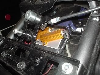
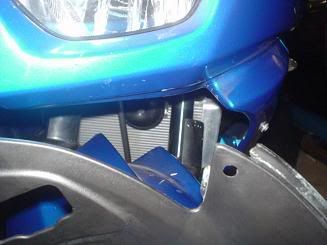
I mounted mine above the IC box (That box that sits directly beneath the reat seat cowl unlock). Resistors these size displace heat so that's why they have heat sinks. Don't mount these to plastic (or heaven forbid to the IC box). I cut a piece of aluminum sheet and mounted the resistors to it as you can see in the picture. This way:
A) aluminum dissipates heat stupid fast.
B) It's uncluttered.
C) It downright looks spiffy.

These resistors "take up the slack" of (TWO) 12v incandescent bulbs each (These resistors are 6 ohm,
50 watt). You need one for EACH blinker circuit as well. Since I went ahead and replaced my front turn signals with LED ones these sufficed. If you're only going to replace the rear turn signals you'll still need two resistors, but half the size (10 ohm,
25 watt). As for the wiring, there are (2) two-wire harnesses that lead from the tail of the bike and connect somewhere above the fuse box. One is black and one is gray and they are probably next to each other. You can test this by simply pulling both and seeing if the rear turn signals work (They shouldn't). Then wire each resistor as if if were a bulb.
For the right turn signal (when viewed from the back of the bike) wire one of the resistors (preferably before the connector as it will allow you to still unplug the connector to remove the rear tail assembly if you need to) to Grey wire for the (+) circuit and to the black/yellow wire for the (-) circuit for the resistor.
For the left side signal (again when viewed from the back of the bike and again splice it preferably before the connector) the wires should be green for the (+) circuit and black/yellow again for the (-) circuit.
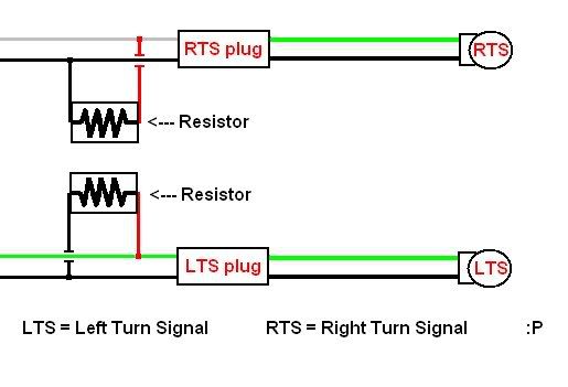
If you're a masochist you can splice the resistors ahead of the connector (but will lose the ability to unplug the connectors and pull the tail section from the bike completely off). The (+) signal going to the bulbs in this case is green for both sides and the (-) signal is still the black/yellow.
You can now replace the rear turn signals with LED's and/or the front ones as well and not have to worry about upsetting the flasher
Step 2 - Wiring alternating flashers/running lights
This is something I wanted to do as I've always thought it was cool how cars did it. While cars run incandescent bulbs for the side marker lamps/turn signals, I'm running LED's and it cornfuses things so I had to install (2) relays (one for each turn signal circuit) to accomplish this. So my peg mounted signals act as running lights and are on as long as the motorcycle is on. When I activate a turn signal circuit that side's peg mounted signal will turn off and the tail-mounted signal will light up. Then after that blink the peg signal lights again and then cycle repeats as long as that blinker circuit is activated...
Here's how I wired it:
Some quick notes if you aren't familiar with diagrams:
For one 90% (if I had to guess) of relays sold in stores don't have an 87a (The middle prong) terminal. This is the key to making this work, so don't try it with a regular relay that lacks this terminal! Relays do exactly as their name implies: they relay... Electricity.
I use relays all the time and think they're super. Typically if you have a high current drawing circuit you don't want to have to wire that all the way to a switch with a thick wire and have to find a switch to handle the load. So with a relay you have that large load travel to the relay and onto the circuit you're powering. Then you have a small circuit which "closes" the relay to complete the circuit. Therefore if you're wiring (say with a car) a radiator fan you can have a little 18-22 gauge wire go into the vehicle to a switch.
Ok after that quick lesson on relays, the 87 circuit is the (+) circuit that is activated when the relay is signaled. The 87a is active as long as the relay is NOT activated. So you can see in the diagram that as long as the turn signal signal (terminal 30) isn't on then the 87a circuit IS engaged and the side markers are on. As soon as the relay senses the voltage to turn on the turn signals it opens the circuit going to terminal 87a and hence the tail-turn signals turn off. Confused?

Since LED's draw such little current I mounted each relay (remember one for each circuit) on each side of where I mounted my resistors for the turn signal circuits. I then have one wire (from terminal 87a) going to that sides peg-signal and another wire going to the front of the bike for the OTHER LED turn signals I'll go over in a sec (lots of fun alternation).
Step 3 - Peg mounted signals
Ok, so hopefully you know where the power is coming from for each of the turn signals with that last step
")
. Here's how
I did my peg-mounted turn signals...
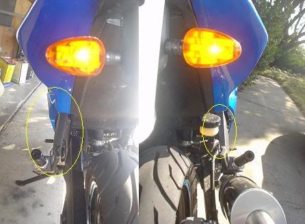
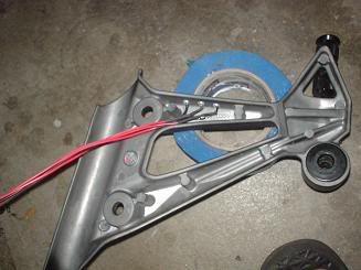
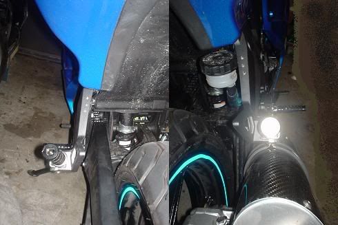
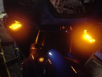
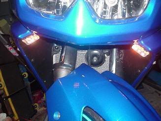
You can see each of the LED turn signals on the tail of the bike and in the background I've circled each passenger peg mount where LED's will be installed. While the rear-brake reservoir partly obscures the right side peg, the reservoir CAN be moved (I'll do a DIY on how I did that later).
So remove each passenger peg mount (very simple, the left side is just two allen bolts and the right side also has the exhaust hanger). The 'trick' after removing them is coming up with a pattern for the LED's beforehand. I did some measurements and thought I'd do 3 LED's per peg (although I think I might add about 3 more in a staggered line per peg one of these days). Mind the LED bulb size you're using! I used 5mm LED's so you can really only fit about 8-10 per peg if you really crammed them. (Although that'd be too bright). Probably 5-6 per peg (if you use 5mm) is ideal.
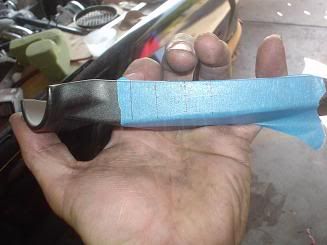
So the 'trick' is to draw equally spaced lines on a piece of masking tape, then align that with the peg at repeatable locations (so each side is identical). Make sure you really press the tape on the peg mount. This eliminates chipping when you finally do drill. Once you have the tape where you want it, tap each spot with a punch and drill! Try to keep the holes for the LED's as small as possible. The LED's should take some effort to push in.
More wiring fun! There are a couple of different ways to wire the LED's. Some people wire every two LED's in series (so they share one small resistor), some wire the whole thing in parallel (so each LED gets a resistor) and some will wire damn near the whole thing in series (so you likely won't need any resistors). I prefer to wire a resistor for each LED. This way if one LED fails only that one LED fails. That and it makes for a clean installation as you don't have to split wires. I ordered my resistors in bulk and each LED included a matching resistor to make it work for a 12.5v system.
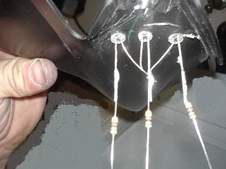
This isn't the peg-mount, but it gives you the idea. One resistor goes on the long LED lead (the postive lead). I just connect all the (-) leads together and solder then together. Then I soldered a 3' long black 16 (although 18 will work just fine) wire to this. For this you might have to have a short span of 18-22 gauge wire to go from the resistors to all meet up. I suggest measuring out the wires and matching the the each LED (so the longest one goes to the furthest LED down and the shortest to the closest one to the top). After you solder these, slide a small shrink tube down each and hit them with heat to shrink them.
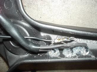
Here I've shrunk-wrapped each individual LED lead, resistor, and wire. After I joined all the wires together further up amd soldered them to one 16 gauge wire about 3' long. I slid a larger shrink-tube down to hold all the wires together and keep them safe. Then I added a little silicone over everything (including the exposed negative leads which also all join and one negative lead travels down to power them). Later on I added incrementally more silicone so everything is sealed.
I then wrapped each peg-mount's black (and I used green for the positive lead) wires together in electrical tape. If you put each peg-mount back on and guide your wire harness to the under-seat area you can then wire the (-) lead to terminal 85 and the positive terminal to terminal 87a. Anytime you need to remove the peg you just pull each plug off it's respective resistor and the mount should come off and the wire harness is free to come out.
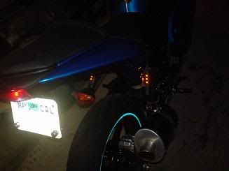
Another comparison shot where you can see the little LED's (They're hard to see when the bike is off)

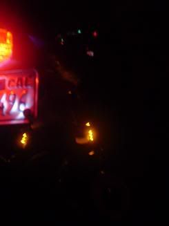
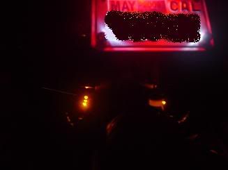
And lit:
 Step 3
 - Front LED's
While I have the alternating circuit I figured I could throw some "hidden" LED's up front as well. Here's what I did:
This little panel runs underneath the headlight area. The corner with the mounting hole in it seems a keen place to throw some LED's!
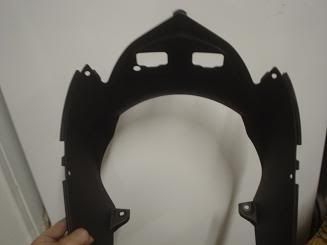
Here's the panel. With this I didn't use masking tape as the panel is un-painted and plastic. I found two common points to each side, and drew a line between them. I think equally spaced spots for mouting the LED's.
Ok, after I did all this the lights weren't bright enough, so I added offset another row behind the first row with 5 more LED's. That STILL didn't quite do it, and I figured there was no forward projection OF the lights so:
I added a polished piece of aluminum BEHIND the two rows and threw 3 LED's in THAT as well. I didn't snap any pictures of the aluminum piece, but all it is is a piece of 3/4" angle aluminum. I cut it long enough so that it ran behind the back row of LED's. I rounded the corners of it and polished the outer side or it. I then cut a slit behind the back LED row and slid it in. After verifying it's tight fitement (excccelent) I'd pull each side out, drill three holes for additional LEDs, and then re-mount. I then drilled one hole per side behind the 'reflector' to run the wires for each side's LED's up. So now there is a total of 11 LED's per side (don't worry about the current draw, that's still next to nil) and they are visible.

The wiring principals are the same as the rear-peg LED's and guess what? These are also wired to the relays that the peg-signals used. So these add an amber glow underneath the headlight and also alternate with the front turn signals.
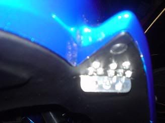
without the headlight on...
with external lights on.
So that's it for the turn signals... I also did something for the brake lights (next post time) ...