Note: This is an example with the measurement (It just happens to be MY example). Your results probably WILL vary, so unlike jetting, you can't use 'basline' numbers. It has to be exact 
So to find the 'new shim' heights here's my math (ALL in inches):
Exhaust valve - Number 1 - Number 2 - Number 3 - Number 4
Lash =
________.0065
_____.0080
_______.0070
_____.0060
Shim =
________.1112
_____.1102
_______.1112
_____.1083
Total =
________.1177
______.1182
______.1182
_____.1143
Intake valve - Number 5 - Number 6 - Number 7 - Number 8
Lash =
_________.0095
_____.0070
_____.0080
_____.0080
Shim =
_________.1112
_____.1112
_____.1112
_____.1112
Total =
_________.1207
_____.1182
_____.1192
_____.1192
Then you subtract what you WANT the total lash to be (in this case I'm looking for .010" on the exhaust and .0085" on the intake). This gives you your 'ideal' shim thickness.
Exhaust valve - Number 1 - Number 2 - Number 3 - Number 4
_____________.1077
_____.1082
_____.1082
______.1043
Intake valve - Number 5 - Number 6 - Number 7 - Number 8
_____________.1122
_____.1097
_____.1107
______.1107
NOW I convert to metric and round to match shims on Kawaski charts:
Exhaust valve - Number 1 - Number 2 - Number 3 - Number 4
______________2.80
______2.75
_______2.75
______2.65
Intake valve - Number 5 - Number 6 - Number 7 - Number 8
______________2.85
______2.80
______2.825
_____2.825
Quote:
|
Originally Posted by alex
Late edit by Vex with some updated information: Where I listed the total lash? That's kind of unnecessary. I think I originally intended on putting the DIFFERENCE in valve lash required so the column should read: Difference from ideal: .0035 .002 .003 .004 for the exhaust and: -.001 .0015 .0005 .0005 for the intake. Formatting is a pain in the butt for those to get the spacing so I apologize in advance for that.
|
Whammy!
Got things back together and here are some notable things upon re-installation:
1.) Remove the two seals that seal the spark plug holes from the underside of the valve cover:
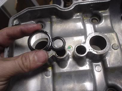
and set them over the holes on the head. I didn't do this at first and one moved and got crushed. This caused an oil leak which I discovered quick enough...
RE-installing the CCT:
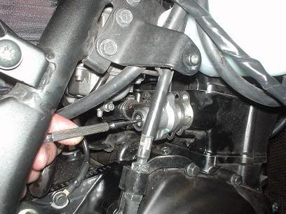
You need to 'reset' the CCT before reinstalling it!! This entails removing the 10mm bolt and inserting a little flat blade screwdriver. You're supposed to turn this clockwise (which in turn causes the shaft to pull backwards into the CCT housing... This is tricky to accomplish in this tight area so I....
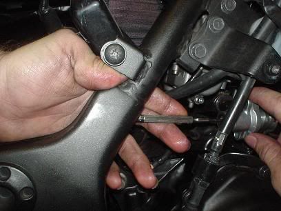
Held the little screwdriver with one hand and turned the housing COUNTER-clockwise (thus doing the same thing as simply turning the screwdriver clockwise). Once you can't turn this any more fully press the housing into the block and put one of the 8mm bolts in to hold things. THEN you can let go of the flat-blade screwdriver, install the other 8mm housing bolt and then lastly the 10mm cap.
_