Quote:
Originally Posted by Ceeloo Yello

Cool, Thank you.
|
(Hope that posting in this thread doesn't piss anybody off. At least it's FI related.)
As promised, here's a few pictures and some documentation of progress on the small project to create a "multi-MAP" for my FI 2005 EX250.
Be Advised: I still use Photobucket, and it seems they (Photobucket) are really thrashing around trying to find a place in this world, so be prepared for the possibility of some weird pop-ups and other presentation oddities/advertising when you're viewing my photos.
Once again, the goal of this small project:
Quote:
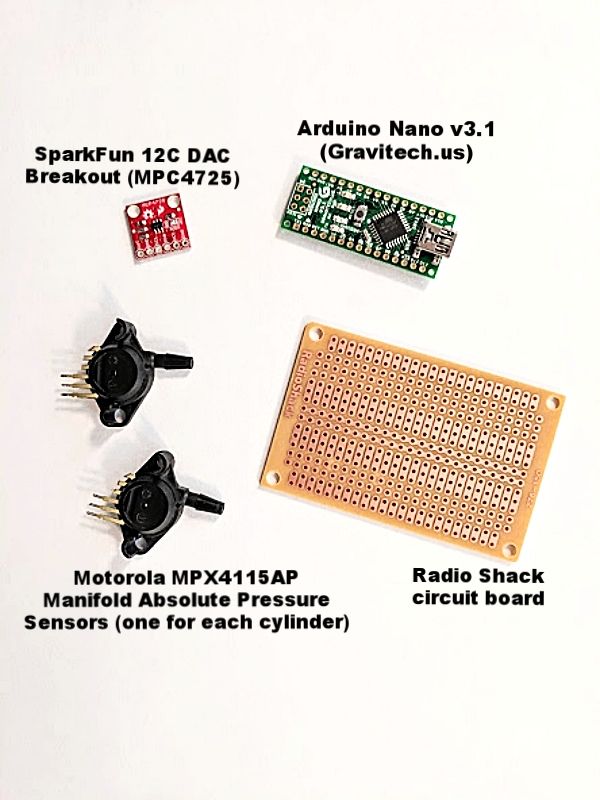
An FI "farkle" that I'm planning to add to the EX250 is an Arduino Nano controlled Manifold Absolute Pressure sensor array (2 MAP sensors for the EX250).
This unit will read simultaneously from a dedicated MAP sensor on each of the two cylinders and it will discriminate for the lower signal (i.e. more vacuum) and then forward only the lower signal (on a microsecond-by-microsecond basis) onward to the MicroSquirt's MAP sensor input line (pin 24 if I remember correctly). Between the Arduino Nano and the MicroSquirt will be a digital to analog converter (DAC) to change the digital Nano output into something the MicroSquirt can use.
This will make the EX250's MAP signal information much more useful to the MicroSquirt. But even with that improvement I'm expecting to run the engine in ITB mode (which is Speed Density when below a certain yet-to-be-decided MAP kPa value, and switching to Alpha N above that value).
Also, the Nano will be monitoring the Cylinder #1 MAP vacuum signal for each time it goes below a pre-specified minimum value. This information will be used to generate the equivalent of a Hall-type Camshaft speed sensor. This will allow the MicroSquirt to run the engine in full sequential mode.
|
Here's a picture of the items:
Here's a picture of the wiring connections I needed to make (there's one error on this picture, the "Vout from MAP #1 to Nano A2" should read "Vout from MAP #1 to A0"):
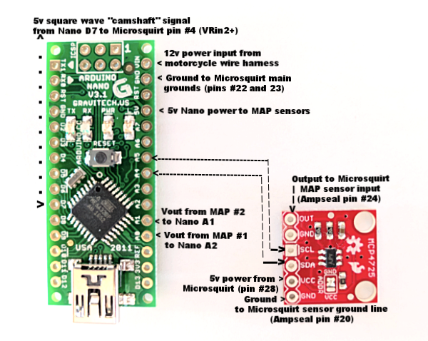
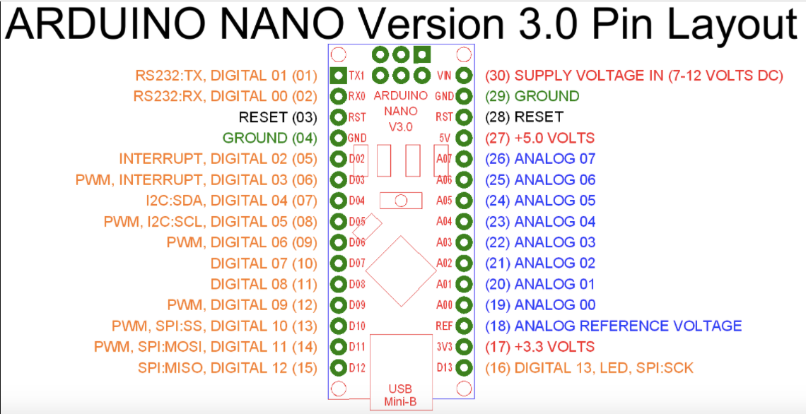
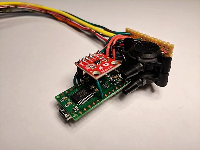
Here's a pic of the Nano's input/output set up:
I use hard, single core wire for all of the connections between the circuit boards (back and forth between the Nano and the DAC). The circuit boards and the MAP sensors will be weather-proofed inside an ABS plastic project box.
I use automotive-grade stranded wire to take inputs to and from the project box. The transitions to-and-from the project (stranded wire to single core wire) occur on the small piece of Radio Shack circuit board.
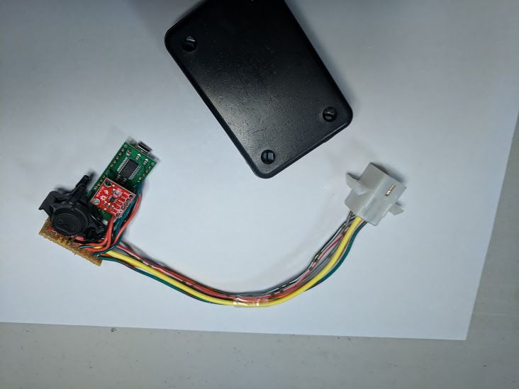
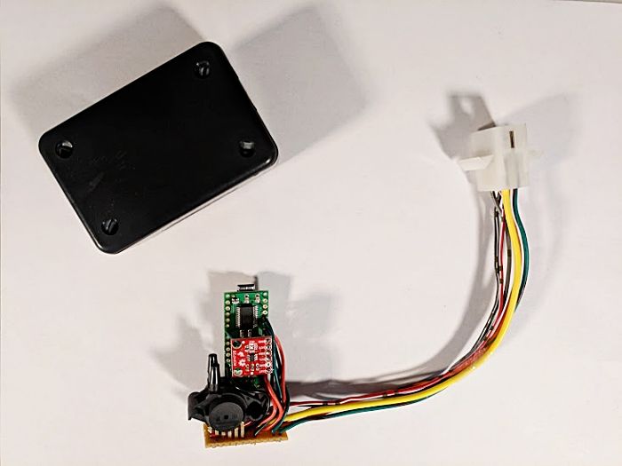
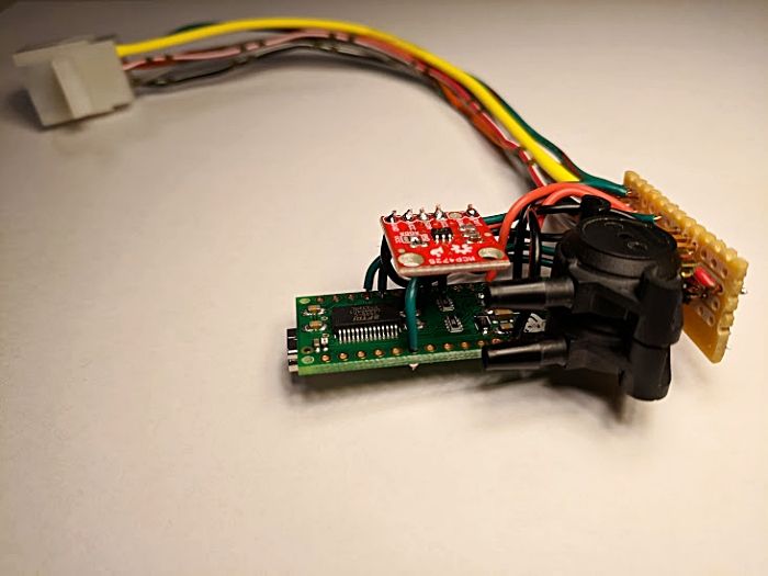
The outputs/inputs that you see running to the multi-plug are:
Red/with White stripe = 12 volt key-switched power from the bike's harness
Black/with White stripe = Ground (to main ECU grounding point)
Yellow = 5 volt square wave "camshaft" output signal to ECU input pin
Green/with Red stripe = Output to ECU MAP sensor input pin
Orange/with Green stripe = 5 volt "sensor power" from ECU
Grey = Ground line to ECU sensor ground point
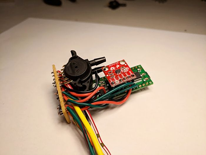
You can see the attachment port (barb) on each of the two MAP sensors. There will be a rubber vacuum hose attached to each of these ports, running to the vacuum ports on the throttle body.