
|
 December 1st, 2008, 04:00 AM
|
#1 |
|
That's me!
Name: TJ
Location: Ames, IA
Join Date: Nov 2008 Motorcycle(s): 2008 Ninja 250r (Tis blue), 2008 CBR600RR Posts: 454
|
Like anything I find I'll do one thing, but then I notice something else that would "accent" that, or something that requires attention because of the first thing... Anywho when I first redid my rear fender I noticed how hard it is to SEE these bikes (especially at night). This further garnered my attention one night heading home from work when I almost ran into a person on another motorcycle doing a windy road. Being his tail light was a dim bulb I couldn't really tell how far ahead this person was (depth perception is difficult if you have little to work with). To to give more dimension to my motorcycle I went buck wild with LED's:
Step 1 - Add resistors to "compensate" for less current: First I replaced the rear turn signals with LED ones. On another forum one of my pet peeves are the countless, "I changed my turn signals to LED's and now they don't blink!"  Drives me batty! The problem is one of current. The flasher gets "hot" when current flows through it. Incandescent bulbs draw a decent amount of power (They're very inefficient compared to LED or halogens). So when current flows through the incandescent bulbs the flasher gets "hot" until it hits the preset temperature in which it breaks the circuit to cool down. Once it cools down enough it closes again (anndddd repeat). The problem with LED turn signals is they draw a LOT less current. So after replacing only your rear turn signals for LED's the flasher allows current to pass, but it never gets hot enough to break the circuit. The solution? Resistors wired in parallel (simply spliced into a circuit) can "mimic" an incandescent bulb. Many eBay sellers sell them and automotive parts suppliers (Kragen, Napa, Discount Auto, etc.) will sell these. 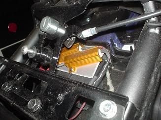 I mounted mine above the IC box (That box that sits directly beneath the reat seat cowl unlock). Resistors these size displace heat so that's why they have heat sinks. Don't mount these to plastic (or heaven forbid to the IC box). I cut a piece of aluminum sheet and mounted the resistors to it as you can see in the picture. This way: A) aluminum dissipates heat stupid fast. B) It's uncluttered. C) It downright looks spiffy.  These resistors "take up the slack" of (TWO) 12v incandescent bulbs each (These resistors are 6 ohm, 50 watt). You need one for EACH blinker circuit as well. Since I went ahead and replaced my front turn signals with LED ones these sufficed. If you're only going to replace the rear turn signals you'll still need two resistors, but half the size (10 ohm, 25 watt). As for the wiring, there are (2) two-wire harnesses that lead from the tail of the bike and connect somewhere above the fuse box. One is black and one is gray and they are probably next to each other. You can test this by simply pulling both and seeing if the rear turn signals work (They shouldn't). Then wire each resistor as if if were a bulb. For the right turn signal (when viewed from the back of the bike) wire one of the resistors (preferably before the connector as it will allow you to still unplug the connector to remove the rear tail assembly if you need to) to Grey wire for the (+) circuit and to the black/yellow wire for the (-) circuit for the resistor. For the left side signal (again when viewed from the back of the bike and again splice it preferably before the connector) the wires should be green for the (+) circuit and black/yellow again for the (-) circuit. 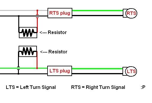 If you're a masochist you can splice the resistors ahead of the connector (but will lose the ability to unplug the connectors and pull the tail section from the bike completely off). The (+) signal going to the bulbs in this case is green for both sides and the (-) signal is still the black/yellow. You can now replace the rear turn signals with LED's and/or the front ones as well and not have to worry about upsetting the flasher Step 2 - Wiring alternating flashers/running lights This is something I wanted to do as I've always thought it was cool how cars did it. While cars run incandescent bulbs for the side marker lamps/turn signals, I'm running LED's and it cornfuses things so I had to install (2) relays (one for each turn signal circuit) to accomplish this. So my peg mounted signals act as running lights and are on as long as the motorcycle is on. When I activate a turn signal circuit that side's peg mounted signal will turn off and the tail-mounted signal will light up. Then after that blink the peg signal lights again and then cycle repeats as long as that blinker circuit is activated... Here's how I wired it:  Some quick notes if you aren't familiar with diagrams: For one 90% (if I had to guess) of relays sold in stores don't have an 87a (The middle prong) terminal. This is the key to making this work, so don't try it with a regular relay that lacks this terminal! Relays do exactly as their name implies: they relay... Electricity. I use relays all the time and think they're super. Typically if you have a high current drawing circuit you don't want to have to wire that all the way to a switch with a thick wire and have to find a switch to handle the load. So with a relay you have that large load travel to the relay and onto the circuit you're powering. Then you have a small circuit which "closes" the relay to complete the circuit. Therefore if you're wiring (say with a car) a radiator fan you can have a little 18-22 gauge wire go into the vehicle to a switch. Ok after that quick lesson on relays, the 87 circuit is the (+) circuit that is activated when the relay is signaled. The 87a is active as long as the relay is NOT activated. So you can see in the diagram that as long as the turn signal signal (terminal 30) isn't on then the 87a circuit IS engaged and the side markers are on. As soon as the relay senses the voltage to turn on the turn signals it opens the circuit going to terminal 87a and hence the tail-turn signals turn off. Confused?  Since LED's draw such little current I mounted each relay (remember one for each circuit) on each side of where I mounted my resistors for the turn signal circuits. I then have one wire (from terminal 87a) going to that sides peg-signal and another wire going to the front of the bike for the OTHER LED turn signals I'll go over in a sec (lots of fun alternation). Step 3 - Peg mounted signals Ok, so hopefully you know where the power is coming from for each of the turn signals with that last step ") . Here's how I did my peg-mounted turn signals... . Here's how I did my peg-mounted turn signals...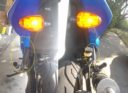 You can see each of the LED turn signals on the tail of the bike and in the background I've circled each passenger peg mount where LED's will be installed. While the rear-brake reservoir partly obscures the right side peg, the reservoir CAN be moved (I'll do a DIY on how I did that later). So remove each passenger peg mount (very simple, the left side is just two allen bolts and the right side also has the exhaust hanger). The 'trick' after removing them is coming up with a pattern for the LED's beforehand. I did some measurements and thought I'd do 3 LED's per peg (although I think I might add about 3 more in a staggered line per peg one of these days). Mind the LED bulb size you're using! I used 5mm LED's so you can really only fit about 8-10 per peg if you really crammed them. (Although that'd be too bright). Probably 5-6 per peg (if you use 5mm) is ideal. 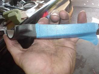 So the 'trick' is to draw equally spaced lines on a piece of masking tape, then align that with the peg at repeatable locations (so each side is identical). Make sure you really press the tape on the peg mount. This eliminates chipping when you finally do drill. Once you have the tape where you want it, tap each spot with a punch and drill! Try to keep the holes for the LED's as small as possible. The LED's should take some effort to push in. 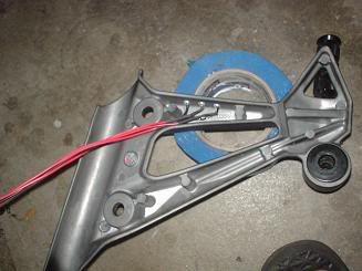 More wiring fun! There are a couple of different ways to wire the LED's. Some people wire every two LED's in series (so they share one small resistor), some wire the whole thing in parallel (so each LED gets a resistor) and some will wire damn near the whole thing in series (so you likely won't need any resistors). I prefer to wire a resistor for each LED. This way if one LED fails only that one LED fails. That and it makes for a clean installation as you don't have to split wires. I ordered my resistors in bulk and each LED included a matching resistor to make it work for a 12.5v system. 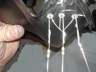 This isn't the peg-mount, but it gives you the idea. One resistor goes on the long LED lead (the postive lead). I just connect all the (-) leads together and solder then together. Then I soldered a 3' long black 16 (although 18 will work just fine) wire to this. For this you might have to have a short span of 18-22 gauge wire to go from the resistors to all meet up. I suggest measuring out the wires and matching the the each LED (so the longest one goes to the furthest LED down and the shortest to the closest one to the top). After you solder these, slide a small shrink tube down each and hit them with heat to shrink them. 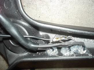 Here I've shrunk-wrapped each individual LED lead, resistor, and wire. After I joined all the wires together further up amd soldered them to one 16 gauge wire about 3' long. I slid a larger shrink-tube down to hold all the wires together and keep them safe. Then I added a little silicone over everything (including the exposed negative leads which also all join and one negative lead travels down to power them). Later on I added incrementally more silicone so everything is sealed. I then wrapped each peg-mount's black (and I used green for the positive lead) wires together in electrical tape. If you put each peg-mount back on and guide your wire harness to the under-seat area you can then wire the (-) lead to terminal 85 and the positive terminal to terminal 87a. Anytime you need to remove the peg you just pull each plug off it's respective resistor and the mount should come off and the wire harness is free to come out. 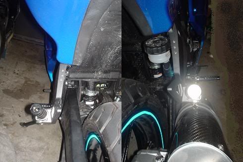 Another comparison shot where you can see the little LED's (They're hard to see when the bike is off)  And lit: 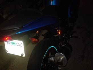 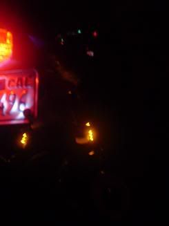 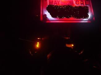 Step 3 - Front LED's While I have the alternating circuit I figured I could throw some "hidden" LED's up front as well. Here's what I did: 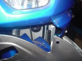 This little panel runs underneath the headlight area. The corner with the mounting hole in it seems a keen place to throw some LED's! 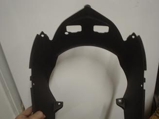 Here's the panel. With this I didn't use masking tape as the panel is un-painted and plastic. I found two common points to each side, and drew a line between them. I think equally spaced spots for mouting the LED's. Ok, after I did all this the lights weren't bright enough, so I added offset another row behind the first row with 5 more LED's. That STILL didn't quite do it, and I figured there was no forward projection OF the lights so: 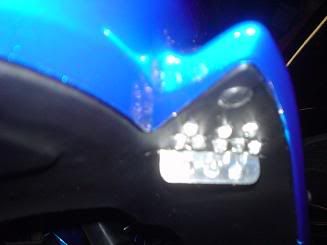 I added a polished piece of aluminum BEHIND the two rows and threw 3 LED's in THAT as well. I didn't snap any pictures of the aluminum piece, but all it is is a piece of 3/4" angle aluminum. I cut it long enough so that it ran behind the back row of LED's. I rounded the corners of it and polished the outer side or it. I then cut a slit behind the back LED row and slid it in. After verifying it's tight fitement (excccelent) I'd pull each side out, drill three holes for additional LEDs, and then re-mount. I then drilled one hole per side behind the 'reflector' to run the wires for each side's LED's up. So now there is a total of 11 LED's per side (don't worry about the current draw, that's still next to nil) and they are visible.  The wiring principals are the same as the rear-peg LED's and guess what? These are also wired to the relays that the peg-signals used. So these add an amber glow underneath the headlight and also alternate with the front turn signals. 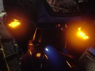 without the headlight on... 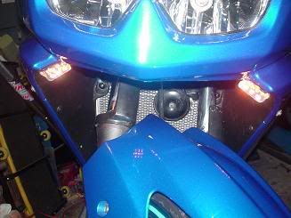 with external lights on. So that's it for the turn signals... I also did something for the brake lights (next post time) ... Last futzed with by VeX; December 1st, 2008 at 05:24 AM. |

|

|
|
December 1st, 2008, 04:01 AM
|
#2 |
|
That's me!
Name: TJ
Location: Ames, IA
Join Date: Nov 2008 Motorcycle(s): 2008 Ninja 250r (Tis blue), 2008 CBR600RR Posts: 454
|
Ok, I wanted the strips that a lot of the GSXR's have in the back for the brake lights. I was going to make strips out of diffuser panels and then mount LED's behind it for a smooth light stream. The problem is some of the real estate atop the mudflap is limited! (Especially the area underneath the IC box). So I opted to drill and mount strips of individual LED's (I'm crazy I know). To further complicate this I wanted a running light set of strips and a brake light set of strips. So the outer rows are always lit, and the inner rows only light when you activate the brakes. To really emphasize the brake light I also packed the LED's tighter together on the middle rows (3 LED's for every 1 outer LED)...
I didn't really write-up a formal DIY on this as It's not overly complicated, but more tedious. First you have to remove the mudflap. Then on the backside I laid down 4-strips of masking tape. Down each masking tape strip I drew perfectly straight lines. Then I drew intersecting lines for every desired LED. After drilling all the LED holes peel back the masking tape and I cleaned up the outer part (the visible side) of each hole with a stepped drill bit. Just a little "umphh" per hole is all you need. You're just aiming for somewhat bevel each hole to deburr it and give it a clean look. Again make the holes small so the LED's really have to be forced in. Then push LED's in holes The trick here is to make sure the strips of LED's all have the positive leads and negative leads lined up. For each side I had the positive leads facing outwards and the negative leads facing inward. This way I literally tied all the negative leads together down each side and soldered it all together...Tip! - ALL hardware stores sell liquid electrical tape. I went buck wild with this stuff. With the negative leads I brushed liquid electrical tape in multiple coats over it all. Get freaky with the stuff. I also painted the backsides of each LED with it to prevent possible arcing if water gets in there or if things move. Like everything else I soldered a resistor to each LED lead (all 46 of them) and had to pick up a couple of packs of small shrink tubes from Home Depot. Again you don't have to wire them this way, but it's really not that difficult to solder that many resistors once you get going with it! When all's said and done the back of the mudflap looks like strips of firecrackers tied together . Wiring-wise you can wire the running-light strips to terminal 86 on either of your two previously installed relays (Always +12 volts when IGN is on) and for the brake light strips you just splice into the either the blue wire (if you're coming right from the tail light) or the blue/red wire (if you're before the connector). Again LED's don't draw much current so the 30 or so LED's that are in the 'brake light circuit' won't even phase the total current draw. For the visual people, here's the final product:  There they are! Again the inner strips are the 'brake lights' and the outer strips are the running lights. So in action: 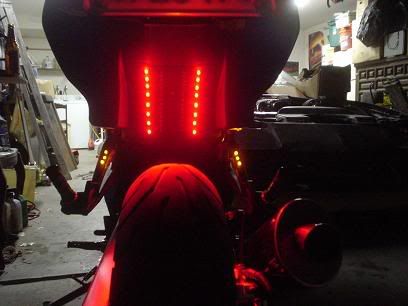 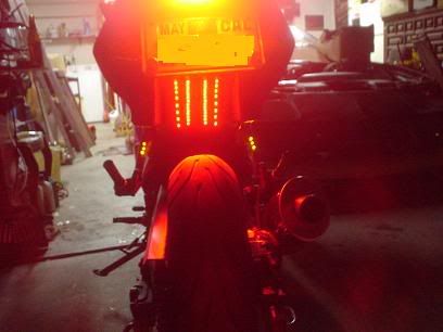 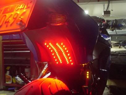 I've since updated these pictures. Notice there's no rear-brake reservoir to obscure the side markers? This makes me happy
|
|
|
|
|
December 1st, 2008, 11:27 AM
|
#3 |
|
Join Date: Nov 2008 Posts: Too much.
|
The mother ship awaits you, lord Vex...
 Great job, as usual. Are those LEDs mounted to the rear peg red or clear? They look a bit bright, so it's hard to tell what color they are. How about a shot of the entire bike from about 15-20 ft away at night? 
|
|
|
|
|
December 5th, 2008, 12:57 AM
|
#4 |
|
ninjette.org member
Name: Felix
Location: Brisbane, Australia
Join Date: Nov 2008 Motorcycle(s): 08 ZX6R Posts: 38
|
This is my VEX inspired mods... (sorry for big pics)
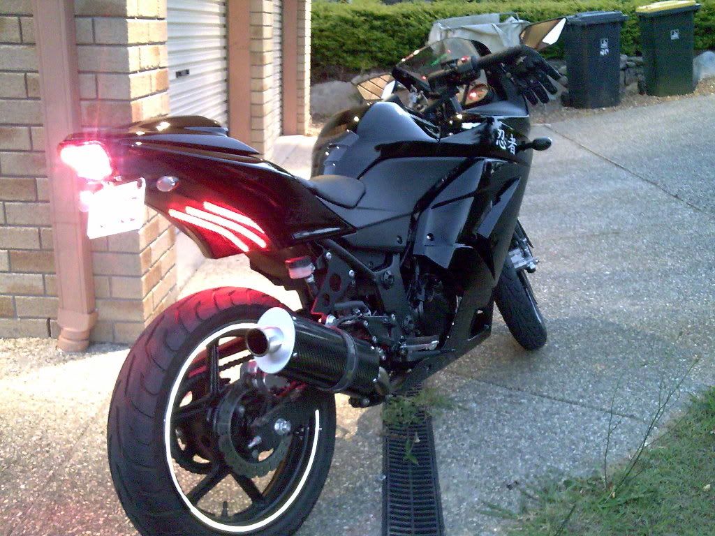 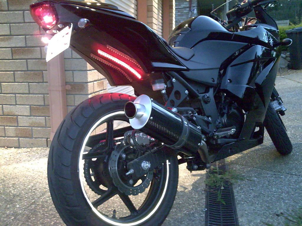 Video of the gear in action... |
|
|
|
|
December 13th, 2008, 04:37 PM
|
#5 |
|
============
Name: Nick
Location: Occoquan, VA
Join Date: Nov 2008 Motorcycle(s): '09 Ninja 250R Posts: 518
|
A few more lights and you'll be able to be seen from outer space.
Looks good!
|
|
|
|
|
December 13th, 2008, 04:43 PM
|
#6 |
|
IC2(SW)
Name: Kerry
Location: Pensacola
Join Date: Nov 2008 Motorcycle(s): . Posts: A lot.
|
You guys are pretty crazy on the LED's! What do you have planned for your helmets & outter wear? Unless you already have something
|
|
|
|
|
December 13th, 2008, 04:52 PM
|
#7 |
|
That's me!
Name: TJ
Location: Ames, IA
Join Date: Nov 2008 Motorcycle(s): 2008 Ninja 250r (Tis blue), 2008 CBR600RR Posts: 454
|
You'd be surprised! The lights are placed such they they look like they're SUPPOSED to be there. I keep meaning on snapping a night pic, but oh well
 It's when you start throwing blue under-lighting under the fairings and the like when you attract the attention of the fuzz, and it stops looking so 'natural' Oh, and Kkim, the rear peg-mounted LED's and the front ones are amber. They're LED's, so they're clear when they're not 'on'. |
|
|
|
|
December 29th, 2008, 06:40 PM
|
#8 |
|
ninjette.org certified postwhore
Name: Bob
Location: CA
Join Date: Dec 2008 Motorcycle(s): '08 Ninja 250r, '14 CBR500r Posts: A lot.
|
Somewhere I saw a jacket that had LEDs under the fabric on the back and down the arms (brake and turn signals).... a little overkill in the clothing, but interesting. I could see doing a break light in back of the helmet if done tastefully and triggered wirelessly.
|
|
|
|
|
December 29th, 2008, 08:53 PM
|
#9 |
|
ninjette.org member
Name: Trista
Location: Ontario, Canada
Join Date: Dec 2008 Motorcycle(s): '08 EX650R Green Kawasaki ninja Posts: 120
|
They look great.
|
|
|
|
|
December 8th, 2010, 01:22 PM
|
#10 |
|
ninjette.org newbie
Name: faiz
Location: Kuala Lumpur
Join Date: Oct 2010 Motorcycle(s): Ninja 250R Posts: 2
|
bro
If I use 4 LED signal for the ninja 250r, how many resistors I should use? 2 or 4? |
|
|
|
|
December 9th, 2010, 08:42 AM
|
#11 |
|
ninjette.org certified postwhore
Name: Alex
Location: Belfast, ME
Join Date: Jul 2008 Motorcycle(s): 2010 Honda NT-700-V, formerly, Green 2008 Ninja 250R Posts: A lot.
|
Vex, Beautifully done! My stance has always been that you cannot have enough lights--especially when they are set up in such a way that it forces the cager or other cyclist to "look again"--what was that?? We need a motto like "Lights Save Lives" This new LED technology allows us to have nice bright lights without overly taxing our low wattage electrical systems.
__________________________________________________
Ninjette, Sold. New Bike: 2010 Honda NT-700V/VA, 73 Honda 550, 74 Honda 550 |
|
|
|
|
December 26th, 2010, 09:38 PM
|
#12 |
|
ninjette.org member
Name: Saint
Location: Japan
Join Date: Dec 2010 Motorcycle(s): 2009 KAW Ninja250r Posts: 72
|
I have to agree that stock, the Ninja 250 sucks on the safety side of the house. The exhaust is never heard and you can't be seen from the sides or the back. I speak from experience cause I'm currently recovering from being hit by a car that did an illegal u-turn in the middle of the night with no headlights on. I'm limping around on a cane 4 months after the accident (100% other person's fault so all medical paid for including a new ride).
For the being seen part, I picked up a Stingerz LED Sports bike basic package (green). I highly recommend this LED kit because it's bright as hell. People will see your LED's before they will see your headlight. I bought the package because I'm lazy and didn't want to go way overboard and create my own. http://www.customdynamics.com/stinge...ent_lights.htm BTW I didn't need to mod anything, runs great off of my stock electrical system. For the exhaust I replaced the stock with a Jardine RT5 slip-on. I live in Japan and EVERYONE runs Yosh exhaust on everything from 50cc scooters and up. My exhaust turns heads everywhere I go because no one is used to the unique sound that the Jardine has. I love it. I've even made my own custom decals out of Arlon and 3M reflective vinyl for the sides and undertail. Bought from ebay some green reflective rim stripes also. I'll try and take some pictures whenever I can and post them. I highly recommend custom decals from reflective material, it looks so sweet. |
|
|
|
|
December 26th, 2010, 10:51 PM
|
#13 | |
|
ninjette.org certified postwhore
Name: Bob
Location: CA
Join Date: Dec 2008 Motorcycle(s): '08 Ninja 250r, '14 CBR500r Posts: A lot.
|
Quote:
 : :
__________________________________________________
Honda Interceptor VFR800 DLX (2014, 8th gen) Honda CBR500r (2014) - FOR SALE Kawi Ninja 250r (2008) - Restored and passed-down within family, only to be abandoned |
|
|
|
|
|
December 26th, 2010, 10:53 PM
|
#14 | |
|
ninjette.org member
Name: Saint
Location: Japan
Join Date: Dec 2010 Motorcycle(s): 2009 KAW Ninja250r Posts: 72
|
Quote:
|
|
|
|
|
|
September 30th, 2011, 09:25 PM
|
#15 |
|
ninjette.org member
Name: Pete
Location: Perth Australia
Join Date: Jun 2011 Motorcycle(s): 2009 ninja 250r Posts: 75
|
ah hah, I wish I had of found this thread earlier, I am forum illiterate, I 've been searching high and low and finally found a wiring diagram that makes sense for the resistors, I asked the sellers how to wire them up they said just wire them up, I ask for a diagram they ask for photo's, What The?.... Thank you Vex finally shed some light on my situation.

__________________________________________________

|
|
|
|
|
June 27th, 2012, 02:08 PM
|
#16 |
|
"scandal!"
Name: Adan
Location: Somewhere
Join Date: May 2011 Motorcycle(s): 2011 250R(Crashed 2/26/2014), 09 ER6n Posts: 660
|
I saw this thread about a year ago when I first got my ninjette and now the time has come.
I have some questions for you VEX if you would please answer them. How good are the peg mounted turn signals in the day time to other viewers i.e, cagers? Is step two really necessary or is it just a neat addition? |
|
|
|
|
June 29th, 2012, 12:03 AM
|
#17 |
|
ninjette.org certified postwhore
Name: Bob
Location: CA
Join Date: Dec 2008 Motorcycle(s): '08 Ninja 250r, '14 CBR500r Posts: A lot.
|
I he still around? I haven't seen him in ages. I think his primary stomping ground may still be at KF. You may want to send him a PM, because I doubt he'll see this.
__________________________________________________
Honda Interceptor VFR800 DLX (2014, 8th gen) Honda CBR500r (2014) - FOR SALE Kawi Ninja 250r (2008) - Restored and passed-down within family, only to be abandoned |
|
|
|
 |
 Similar Threads
|
||||
| Thread | Thread Starter | Forum | Replies | Last Post |
| Wiring LED strips as brake lights, turn signals, and "day-time lights" | blackninja18 | 2008 - 2012 Ninja 250R Farkles | 32 | August 7th, 2013 03:41 PM |
| Thread Tools | |
|
|


