First at all thanks for all the help, opinions, suggestions etc I have received from this forum to make this project a success. Also thanks to Matt from Ecotrons for being so helpful through the entire process.
Difficulty: Medium (not really that hard to be honnest just requires some knowledge about EFI systems, patience and so ingenuity to solve small issues that you might run in to)
- If you don't know anything about EFI systems I suggest you buy a book like
THIS , it honestly helped me a lot to understand what a EFI does and how it does it.
Time required: Took me 3 half Sundays, this includes the time consumed trying to look for solutions and best way to do stuff, so if you follow this guide i bet you will take less than me, you might be able to do it in a weekend if you dedicate the time and effort for it.
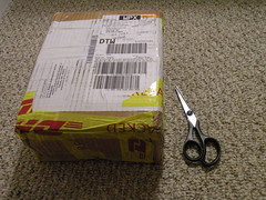
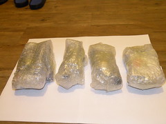
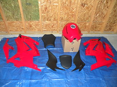
The KIT:
Kit's Packaging
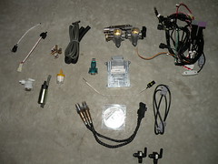 Components (source: ecotrons.com):
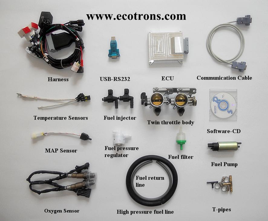
ECU
Harness
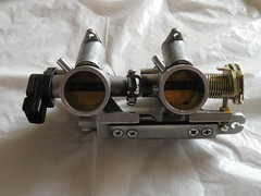
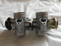
Throttle Body (twin 28mm Throttle body (including TPS sensor)
2x Fuel injector (80g/min)
Fuel pump assembly (Fuel pump (25L/h)
Fuel pressure regulator(3bar)
Fuel filter
fuel hoses and clamps
MAP sensor (1.05bar)
Engine temperature sensor
Intake air temperature sensor
2x Oxygen sensor and bungs
Serial communication cable (to a computer)
Serial to USB converter (optional)
CD - free tuning software
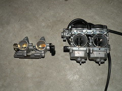
The 28mm dual Throttle body and manifolds
 Installation:
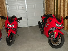
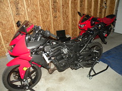
- I decided to install it in mine (right) and leave my wife's bike (left) untouched so i can compre the results later on, either way she wouldn't let me take hers apart

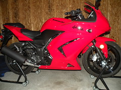
1 - Remove the fairing of the bike as described in
DIY- Let's Get Nekkid!!! THANKS KKIM!
2 - Drain the fuel tank by first disconnecting the vacuum line from the petcock (to avoid flowing fuel, make sure the it is in the ON position), removing the fuel line that goes from the carbs to the petcok (i removed it at the carbs without spilling but you could put a rag in place just in case). Use a funnel and a gas container to safely store the fuel. once you have the funnel and container in place, open the petcock by setting it to the PRI position with a flat screwdriver. at this point you can open the fuel gas tank to speedup the draining.
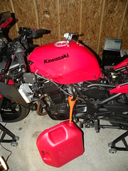
3 - Remove the fuel tank from the bike as described in
DIY- How to Remove the Gas Tank Thanks again to KKIM!. At this point your bike should look like this:
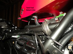
 Gas Tank Modification
4 - You will need to add a return line to the fuel tank. If you are a lucky one with a Cali spec bike you could use the fuel return line that comes already in that tank. For the rest of us, you will need to create your own, here is what I did for mine:
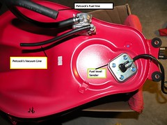
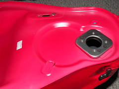
- Remove the petcock and the fuel level sender.
- Remove the paint in a small round section of the bottom of the tank, Choose a flat (not curved) surface so the new fitting will seat flat on the wall of the tank
- Cut a hole in the tank with the appropriate diameter for the fitting that you choose.
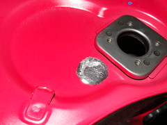
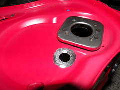
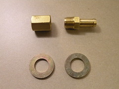
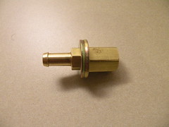
- Here is the fitting I used, a 5/16 brass hose fitting with couple brass washers.
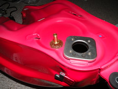
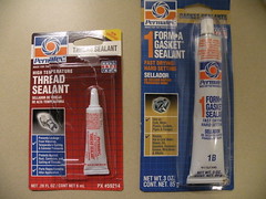
- I carefully placed the fitting in the tank by holding the other end from the fuel level sender hole. You can use a gasket sealant to seal the fitting, but make sure that you use a sealant resistant to gasoline. you can now re-install the petcock and the fuel level sender, but allow the sealant to dry before you can use the tank again. I left it drying 24 hours before using it.
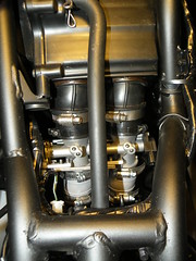
5- Throttle body installation:
- You will now be ready to install the throttle body, first we need to remove the carbs as instructed in by TheDuck
HERE, thanks to Da Duckman!
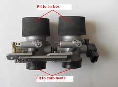
- Install the rubber rings that come with the kit, they will allow you fit the carbs boots that came with the bike to the new throttle. the kit also comes with adapter boots that connects to the existing air box.
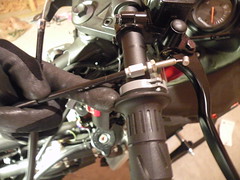
- next, install the accelerator cable into the throttle body. for now, I'm not using the de-acceleration cable, so I just removed it [
Read Update Below, I ended up re-installing the De-acceleration cable]. Remember to adjust the cable play after installation, the manual's spec says around 2-3mm play.
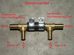
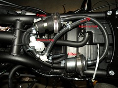
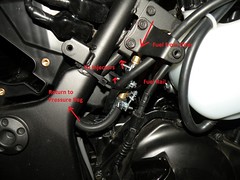
6- Fuel Lines Installation:
Below is the fuel system schematics taken from the installation manual tha comes with the kit
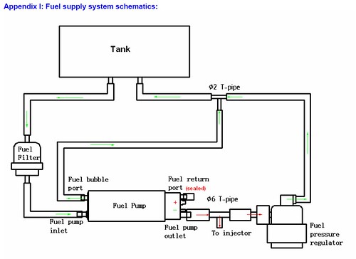
I however replaced the filter from the kit with a pressure rated filter and installed it between the pump and the injectors fuel rail. Notice that the pressure regulator is installed after the fuel rail (after the fuel filter), this ensures that the pressure in the rail is set due to the rating in the regulator, if you install the filter after the regulator and before the rail, you will have a pressure drop due to the filter flow restriction.
 System Sensors
- The system uses several sensors to monitor in real-time the engine, ambient conditions, and user's demand to ensure the optimal Air/Fuel ratio.
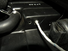
Air Temperature Sensor:
- I installed the air temperature sensor in the same location than the OEM EFI bikes, at the top of the Air Filter Box. However, if you modified/removed the filter box you will have to find a new location for the sensor, for example inside housing of your filter pods.
- First drill a hole slightly bigger than the sensor's diameter. Use a rubber seal to ensure that the sensor will remain in place and will not come off.
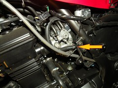
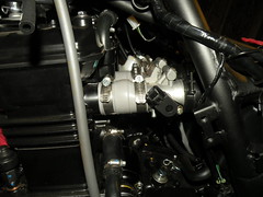
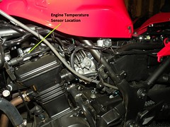
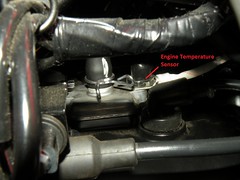
 Engine Temperature Sensor
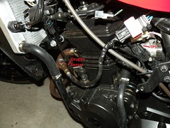
- I installed the engine temperature sensor right in top of the engine, this way it will give a close estimate of the engine head temperature.
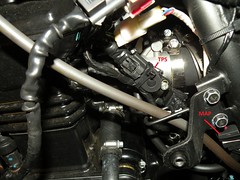
 Throttle Position Sensor (TPS)
- the Throttle position sensor comes already pre-installed in the throttle-body/manifold. So all is left is connect the electrical connector on it.
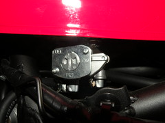
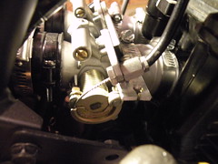
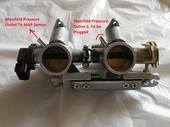
 Manifold Absolute Pressure sensor (MAP):
- The MAP sensor measures the pressure of the air in the manifold (Same as Throttle body assembly in this case) to determinate the amount of air coming into the engine. The throttle body in this kit is made out two single throttle bodies joined, for this reason you will see two manifold pressure outlets but we will need only one, the other
NEEDS! to be plugged to avoid air leakage into the engine. I plugged mine with a small rubber cap and a small hose clamp.
- Use the outlet for the cylinder #1 (this is the one in the left hand side when your are setting on the bike), and plug the second outlet. If you do not plug the other outlet, air will be allowed to enter the cylinder#2, bypass the throttle body's plate and the system will believe you want to accelerate, as a result you will end up with and unbalance and accelerated engine. Ask me how I know
")
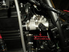
- The manifold pressure outlet form the throttle body assembly/ manifold, is connected to the MAP sensor through a small rubber hose. When choosing the location of the MAP sensor, make sure you don't bend the hose to the point of obstructing the air flow, otherwise you wont read the real air pressure of the manifold.
Oxygen Sensors:
- One of the beauties of EFI is the usage of oxygen sensors that will allow a closed loop control system, this is, the system will monitor the amount of oxygen at the exhaust and determine if the previously burned Air/Fuel (A/F) resulted in a lean or rich condition, so it can fine tune itself to bring back the A/F back to optimal, additionally the system can learn from this fine tuning, and save it in memory so next time the engine is in a similar situation the mixture will be delivered already corrected. This kit have the ability to monitor and control two loops, in this case each loop is used for each cylinder so it can fine tune each cylinder independently, so you will need to install 2 oxygen sensors that are already included.
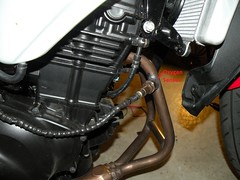
- I have chosen to install the sensor close to the engine so the heat of exhaust gases will help to heat up the sensor. notice that the Oxygen sensor only work after they have heated up. I took my exhaust pipe to a local welding shop to have the sensor bungs welded to the pipes.
-
Be careful where you have the welding done, many muffler shops where I took it told me they could not do the job because the pipe was too small (diameter) and they were afraid the their big torch tools could just cut right trough it. Usually a welding shop have more specialize tools and have more experience doing small jobs like this. It only took about 1 hour in my case.
- Here is location of both sensors after re-installing the exhaust pipe into the engine block:
 EFI's ECU (Computer) "The Brain":
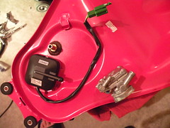
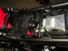
- I connected each single sensor to the harness provided and routed the harness towards the EFI ECU which I located where the Ignition controller was located, relocated the ignition controller in top of the battery, and relocated the relays from the top of the battery to the frame close to the battery.
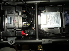
- You will need to connect the negative wire (
-12V, Black on the kit) to the negative of the battery, the
12+V Red wire on the kit to the positive of the battery, to provide power to the ECU.
- The ECU needs to sense the presence of the Key in the ON position in order to begin the pre-pump cycle, commanding the pump to give the fuel line the required pressure before turning on the engine. For this, you will need to tap the
KEYSW (Pink) wire on the harness of the kit to the
Brown/
Black (BR/BK) wire in the Ignition Controller unit, this is a 10A fused line that will provide 12+V and enough current for the ECU when the Key is in the ON position. Note: I tried taping to the Gray wire in the Ignition Controller that supposed to give me the same signal when ON, but this did not provide enough current, so the ECU will not operate, bump!.
- Additionally the ECU need to know the engine speed and Crank position in order to know when to activate the injectors. for this you will need to tap the crank position sensor as follow:
CKP, ORANGE wire in the kit to the
Yellow (Y) Wire in the Ignition controller (this is the positive of the Crankshaft position sensor), and the
GND, GREEN on the KIT (Crankshaft sensor ground) to the
BLACK/
WHITE in the Ignition Controller.
Testing
- before you attempt to turn the engine on, let make sure that we connected everything to the harness:
- turn the key to the ON position, and make sure that you hear the pump working for few seconds, this is to pre-pressurize the fuel lines before ignition.
- If it does, now check the Check Engine lamp, and see if it is ON. If it is, something might be wrong, if this is the case you might want to connect the serial port to the PC and read the DTC from the system, it will tell you what the ECU is complaining about, for example a sensor (if you forgot to connected).
- If the pump turns on, and the ECU does not complains with a Check Engine Light, all should be good to give it a initial try. Turn that baby ON!
Iddle Speed Adjustment:
- The final adjustment is the idle speed, the throttle body have an idle screw that you can rotate to adjust the idle speed. However, ecotrons told me they already pre-adjusted it for us, so we should not mess with it unless you notice that your bike is not idling at the right speed and if it is you have already verified that the problem is not a air leakage. Ask me how I know!
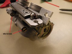
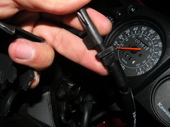
- I set my idle speed by turning the idle screws on the throttle body, while having my laptop connected to the ECU, that way I could have in the software the correct idle reading. I set it to about 1350, just as the manual says. I know some prefer to rise it to about 1500, so it is your choice. Be sure that you adjust the screw the same amount for both cylinders, otherwise you will end-up with an unbalance engine that would not idle correctly
Final Re-Assembly:
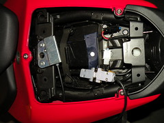
Serial port:
- For final reassembly you will need to find a place for the serial port, you will want a place that is easily accessible without having to take any fairing off, I have placed it on the second seat compartment, that way if i need to connect it to my laptop I just have to remove the rear seat, That location will even make it easier to log data on the road, I usually connect it to my laptop which I carry in my backpack when I want to gather data and see how the system is doing.
 Check Engine Light and RICH/ECO mode Switch
:
- I will leave the location of these 2 to your choice. I decided not to locate the check engine light in the dash since I'm planning to install a KOSO dash which have an input for the Check Engine light already. The RICH/ECO mode switch I'm planning on installing it on the right handle bellow the engine kill switch, but I still have to find a nice switch that will look good.
- The rest is to put the fairing together by following the
DIY- Let's Get Nekkid!!!, by KKIM, in reverse.
Personal opinion about the results:
- First, the kit was really not to difficult to install, this was the first time I ever took a bike apart, and I got it done!, just take the time to do it right and do not rush. having some knowledge about EFI system will definitely help, although the instructions that came with the kitt will get you through, hopefully this DYI helps you as well.
- Performance wise, I was surprised how much improvement can you get with this mod:
- Throttle response is much crisper, the throttle response is much faster without any lag. My EFI bike now redlines much quicker than before.
- Acceleration seems stronger too, I mentioned that I have a twin bike (my wife's) which remains carburated, and after driving mine, hers seems laggy to reach the 60's.
- Unfortunately, I have no dyno number to prove it, BUT I'M REALLY HAPPY WITH MY EFI kit and do not regret the change.
- Top Speed, I reached 95 @ 12kRPM.
Tested on the tracks of course, keep it legal. Notice that besides removing the snorkel, I have not made any other mods, the bike still have stock airbox, and stock exhaust pipe and stock muffler, which I plan on upgrading in the future.
- Fuel Economy, Well these bike are already great in that field, so not much change here. I measured the mileage 3 time (3 full tanks) and consistently got 225-235 miles per 4.2gallons, which makes 53-56MPG. Notice, that I drive 80% highway at highway speed, which means high RPMs in these bikes, and usually shift at 9kRPM and occasionally redline from time to time. I hear shifting a 6kRPM gives you a better MPG, but I like the fun. According to the kits information, the ECU also have a Fuel cut-off feature that cuts the fuel when we close the throttle from a high RPM, i.e when stopping for a red light, that way the engine does not waste fuel if you just want to stop, so that should save some gas.
- Cold engine start, This is a really nice improvement. I usually leave to work early morning, and live in a mostly cold weather, OHIO. The bike rarely turned on at the first attempt when carburated, even when I have it choked all the way. Now, it will turn on right away, and the RPM is pretty stable allowing you to ride on right away if you need to. However, I usually wait few seconds since engines usually get more worn out if you ride them without proper warming, at least that is what I hear. Have you noticed, how unstable is the RPM in cold conditions, it will be really low and stalling until it warms a little, then it will rise to normal idle RPM, this is gone, It will bring the RPM to idle speed right away.
I hope this guide help you along the way if you decide EFI is for you.
PM me of you have any questions,
Forbitel.